CubeUp!
Today’s project serves a couple purposes:
prove an efficiency between two different CAD software
more practice of recursive design
test of detailed print on Creality Ender 3
Software
I first started building this in OpenSCAD because I thought it would be fun to code by hand. It turns out I was right, and it was! Because of the geometry and parametric design, this piece requires very few lines to define in the program and an object can be made which just needs a single variable(n). All told, the design work in OpenSCAD took about 20 minutes.
module board2(n) {
    seq = [0:n:pow(n,2)];
    set = [0:1:n];
    for (a = seq) {
        for (b = seq)   {
            for (c = set)   {
            translate([a,b,0])
            color([(a*.1),(b*.01),(c*.1)])
            cube([n,n,(c+(a+b))]);
            echo(a,b);
            }
        }
    }
}

board2(8);
Line 8, to define color, is irrelevant to the 3D printer. This line of code is merely for my enjoyment as I build the structure. The values in this equation are arbitrary. Line 10 shares an echo of data to the console for debugging.
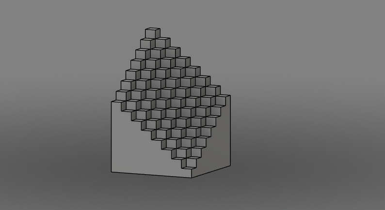
A rendering of cubeUp.stl in OpenSCAD
For comparison, I wanted to test this against Autodesk’s premier application for manufacturing: Fusion 360.
A note about the difference here: OpenSCAD is a code-based modeling software and Fusion 360 is very interface-oriented. To construct or redefine a shape in OpenSCAD, the user must type out lines of code in OpenSCAD'’s C-based language. To construct or redefine a shape in Fusion 360, the user selects a tool and drags their curser across the interface. Little to no understanding of computer language is necessary to operate Fusion 360. This fluency is absolutely necessary to operate OpenSCAD.
In Fusion 360, I used the sketch tool to draw a simple square, then multiply that on a grid to build an 8x8 pattern. Using the extrude tool, I added a “z” dimension to these squares to raise them to a correct height. Note that this process was done in OpenSCAD with recursive “for” loops; in Fusion 360 each extrusion must be done manually. However, the model is now complete! In Fusion 360, the time from sketch to model completion is very short because of the easy interface. All told, the design in Fusion 360 took about 5 minutes.
A note about the two renderings: the image below is an orthogonal view of the model. The image above is a perspective view. This is clear by examining the “tops” of each cube in each image. In the perspective view, cubes near the bottom appear to “tilt down”, because our perspective is from somewhere near the top. The “tops” of each cube on the CGI orthogonal view are the exact same in each iteration, no matter where we positioned the render view. Read more about these view here.
Rendering of cubeUp.f3d in Fusion 360
Recursive Design
This project gave enough practice in recursive design that I must at least mention it. This is something which I try to incorporate in as many projects or practices as I can. This training of creating a vast set of parameters based on a number set’s function of another number set is fantastic for training mathematical capacity. The more math you do, the more you enjoy it (I believe). Since recursive design in OpenSCAD is based on functions, it is very fun to create in.
Print Detail
CubeUp is a fairly solid structure, so a very large print will be both time and material consuming. However since one of the design necessities for this project is size to scale, I can print this at a fairly small size (less than 50 cubic millimetres). As it happens, I misjudged the size in the slicer software and it’s printing even smaller than I had anticipated. This doesn’t seem to effect print quality, and I’m glad to say that the print detail test has been very successful indeed!
Completed cubeUp on Creality Ender 3


